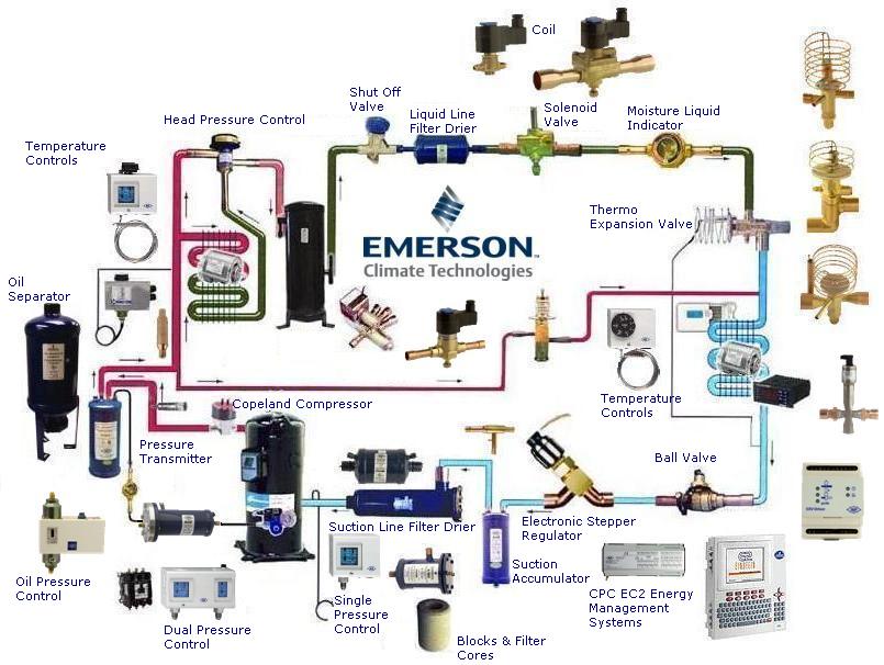
We are an Authorized distributor for Copeland Climate Technologies Flow Controls. Formerly Alco Controls and Emerson Climate Technologies.
Thursday, April 23, 2009
Wednesday, April 22, 2009
Solenoid Valves Nomenclature
200RB5T5M AGM120V -
200R VALVE SERIES, B DESIGN, 5/16" PORT SIZE, COPPER EXTENDED ENDS, 5/8" ODF, MANUAL STEM, 12WATT, CLASS F, JUNCTION, STANDARD 120V/50-60HZ
200RB6F5M AGM120V -
200R VALVE SERIES, B DESIGN, 3/8" PORT SIZE, COPPER EXTENDED ENDS, 5/8" SAE, MANUAL STEM, 12WATT, CLASS F, JUNCTION, STANDARD 120V/50-60HZ
200RB6T4M AGM120V -
200R VALVE SERIES, B DESIGN, 3/8" PORT SIZE, COPPER EXTENDED ENDS, 1/2" ODF, MANUAL STEM, 12WATT, CLASS F, JUNCTION, STANDARD 120V/50-60HZ
Tuesday, April 21, 2009
ARI 730-2005: Flow Capacity Rating of Suction-Line Filters and Suction-Line Filter-Driers
Source: Air-Conditioning and Refrigeration Institute
Scope
This standard establishes a single set of requirements for the testing and rating of ARI standard capacity rating and refrigerant flow rate for refrigerant suction-line filters and filter-driers; whereby, equipment performance can be compared from product to product. The standard covers suction-line filters and suction-line filter-driers in refrigeration and air-conditioning systems.
http://www.ahrinet.org/
Tuesday, April 14, 2009
TI Thermo Valve with interchangeable cartridges
For supermarket cases, walk-in coolers & ice machines applications:
TI[E] thermo valves feature interchangeable cages that provide the capability of changing capacity with the change of a cage. Simply change the easy-to-use cartridges to achieve desired capacity.
- Maximum working pressure: 450psig [3100 kPa]
- 500 hour salt spray resistance per ASTMB117
- Capacities rated in accordance with ARI 750 standards
- Mass spectrometer tested to ensure less than 0.1oz / year R22 [2.5 E-5 std atm/cc/sec] external leakage rate.
Monday, April 06, 2009
Friday, April 03, 2009
Best in class technology

The next time you're installing an EK Filter Drier, make sure you're installing a genuine EK Filter Drier from Emerson Climate Technologies Flow Controls.
Leading Oil Separators
Wednesday, April 01, 2009
Replaceable filter drier blocks and filter cores with STAS
To prevent contamination, do not open can until ready to install.
- Pump down the system and the STAS completely. Warning: System lines must be de-pressurized before attempting to service. Failure to do so can result in system damage and serious bodily injury.
- Remove the cover bolts, cover, and cover gasket (discard old gasket).
- Withdraw the internal assembly by pulling on the handle.
- Disassemble the internal assembly by unscrewing the handle while holding the inlet retainer.
- Remove contaminated filter-drier block. For multiple block units, remove couplings.
- Clean all internal parts thoroughly, giving particular care and attention to outlet screen.
- Remove the block from can and reassemble as rapidly as possible to minimize moisture contamination.
- Replace the screen in the outlet retainer and install the new block or core in the outlet retainer. Make certain that the end of the block with the tapered inside diameter is placed against the outlet retainer. With multiple block units, place coupling between each block or core. Position the inlet retainer over the final block or core, and screw the handle firmly in place. Carefully insert the assembled unit into the shell assembly.
- Lightly coat the new cover gasket with refrigeration oil on both surfaces and carefully place in the groove of the cover.
- Push the cover against the shell assembly. Make certain that the compression spring is against the inlet retainer, and is not handing up on the handle.
- Install 2 cover bolts diagonally opposite holes to hold the cover snugly against the shell edge. Install the remaining bolts snugly.
- Torque all cover bolts evenly in a criss-cross pattern to a torque of 25ft. lbs. maximum for STAS units. For stainless steel bolts in SV series suction line service, the maximum torque is 20ft.lbs.
- Test for leakage.
Subscribe to:
Comments (Atom)
